English
 中文简体
中文简体
Content
The Reliable, Invisible Fastener for Shaft Assemblies
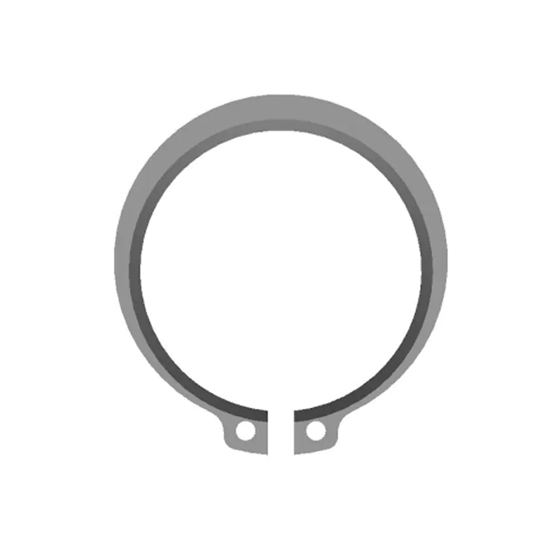
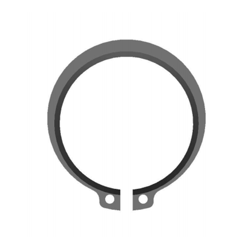
An external retaining ring provides a removable shoulder to precisely locate, secure, and retain components on a shaft. Its core function is to prevent axial movement while transmitting thrust loads without adding significant weight or complexity. Installed into a dedicated groove, this low-profile fastener allows for a compact hub design, eliminating the need for threaded sections, nuts, or bulky collars. Whether in a bicycle gear hub or an automotive transmission shaft, the external circlip delivers a cost-effective, high-strength locating solution that dramatically simplifies assembly and serviceability.
Understanding the Mechanics of a Grooved Joint
The joint's reliability depends on a precise interaction between the ring's inner diameter, the shaft material, and the groove geometry. The ring is intentionally manufactured with an inner diameter slightly smaller than the shaft's groove root diameter. This creates a residual clamping force once installed, ensuring the ring hugs the bottom of the groove and does not float or rattle, a critical factor in preventing fretting corrosion under high-frequency vibration.
How the Interference Fit Prevents Failure
The retention principle is based on elastic deformation. The ring is expanded during installation and then elastically recovers to grip the groove. This means the ring experiences constant tensile stress in its installed state. To prevent premature fatigue failure, the groove shoulder must be square with a sharp, clean edge. A groove with a minimum bottom radius of 0.13mm is standard to reduce stress concentrations, but any larger radius risks the ring climbing out under load, a condition known as "ring dishing." This interference fit is what gives the joint its capacity to absorb intermittent thrust loads far exceeding its static thrust rating.
Correct Installation and Removal Techniques
Improper tooling is the primary cause of ring failure and installation injury. External circlip pliers are not a generic plier; they are a specialized tool with interchangeable tips machined to match specific lug hole diameters. The installation sequence is unforgiving of shortcuts.
The Step-by-Step Procedure for Reliable Assembly
- Tip Selection: Match the plier tips perfectly to the ring's lug holes. A loose fit will damage the lugs; a tight fit will prevent proper spreading.
- Controlled Expansion: Expand the ring only enough to clear the shaft diameter. Over-expansion, beyond the ring's elastic limit, causes permanent deformation, and the ring will not grip the groove base securely after placement.
- Axial Placement: Slide the expanded ring along the shaft to the groove. Do not force it; it should seat naturally.
- Visual Seating Check: Release the pliers and visually verify the ring is uniformly seated in the groove to its full depth around the entire circumference. A rotated ring, with only partial engagement, is a latent assembly failure.
Removal follows the same controlled expansion principle. Often, a screwdriver can be used to dislodge one end from the groove after light expansion, but for production environments, dedicated removal tools with tips that align the lugs and apply uniform force are essential to avoid scarring the shaft.
Decoding Groove Dimensions and Tolerances
The ring is only one half of the fastening system. The groove machined into the shaft dictates joint integrity. The critical dimensions are groove diameter, groove width, and the distance from the groove edge to the shaft end. A standard groove design for a basic external ring typically follows a rule where the groove width is approximately 1.1 to 1.2 times the ring thickness to ensure the ring can seat without binding while minimizing axial end play. The following table shows typical nominal dimensions for a standard-duty external ring for reference shaft diameters.
| Shaft Diameter (mm) | Ring Free ID (approx.) (mm) | Groove Diameter (mm) | Groove Width (mm) |
|---|---|---|---|
| 10 | 9.3 | 9.6 | 1.15 |
| 20 | 18.6 | 19.0 | 1.75 |
| 30 | 28.0 | 28.6 | 2.15 |
Material Selection for Environmental Resistance
The ring material must be compatible with the operating environment and the shaft material to avoid galvanic corrosion. The vast majority of external retaining rings are made from carbon spring steel with a phosphate and oil finish for basic corrosion protection. For demanding environments, this is insufficient, and a conscious material selection is required.
- Standard Duty (Indoor Machines): High-carbon spring steel (SAE 1060-1090), heat-treated to a hardness of HRC 47-52, with a black oxide or phosphate coating.
- Corrosive or Wash-down Environments: Type 302 or 17-7 PH stainless steel. While 17-7 PH provides higher strength after precipitation hardening, 302 offers better ductility for repeated installations on larger diameters.
- High-Temperature Applications: Beryllium copper is an alternative where both corrosion resistance and operating temperatures up to 200°C without significant load loss are required, though it carries a premium cost.
Troubleshooting Common Ring Joint Failures
When a retaining ring fails, the root cause is rarely a defective ring but an incorrect specification or installation. A diagnosis table helps isolate the failure source and implement a corrective action.
| Observed Failure Mode | Probable Cause | Corrective Action |
|---|---|---|
| Ring "dished" or coned | Excessive thrust load; groove radius too large | Use a thicker ring; verify groove corner is sharp |
| Fractured at a lug hole | Over-expansion during installation | Use properly sized pliers and calibrated stop |
| Ring rotates freely in groove | Groove diameter is too large; ring is undersized | Confirm ring and groove to standard (DIN 471/ASME B27.7) |