English
 中文简体
中文简体
Content
Core Function and Engineering Significance of Retaining Rings
Retaining rings serve as the critical mechanical shoulder in precision assemblies, providing a secure method for positioning components on shafts or within bores without the need for threading or complex machining. These fasteners are engineered to absorb axial loads and prevent lateral movement of bearings, gears, and pulleys, effectively replacing bulkier nuts, collars, and cotter pins. The primary advantage of utilizing retaining rings lies in their ability to reduce assembly weight and cost while maintaining high structural integrity under dynamic loading conditions. In modern manufacturing, they are indispensable for creating compact designs where space constraints prohibit traditional fastening methods.
The engineering efficacy of retaining rings depends entirely on the interaction between the ring's elasticity and the precision of the machined groove. When installed correctly, these components distribute thrust loads evenly across the groove walls, preventing stress concentrations that could lead to catastrophic failure. Industry standards dictate that a properly selected retaining ring must withstand axial forces significantly higher than the operational load to account for shock and vibration. Understanding the specific load-bearing characteristics and dimensional tolerances is essential for engineers and maintenance technicians who rely on these components for long-term equipment reliability and safety.

Comprehensive Classification of Retaining Ring Types
Selecting the correct retaining ring begins with understanding the distinct categories available for different mechanical configurations. Each type is designed for specific installation methods and load requirements, making accurate classification vital for successful application.
Internal Retaining Rings for Bore Applications
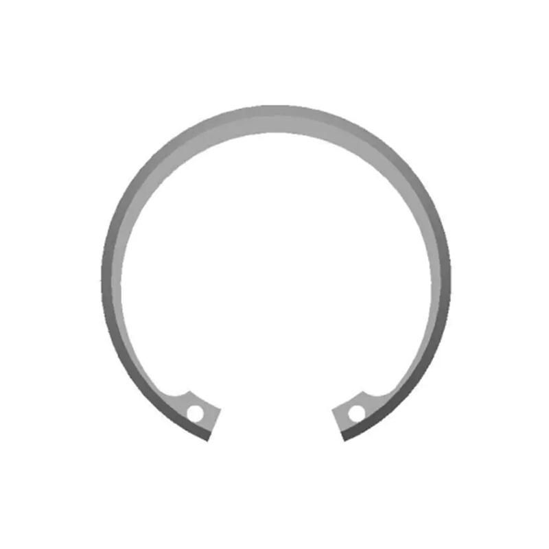
Internal retaining rings are installed inside a cylindrical housing or bore to secure components such as bearings against an internal shoulder. These rings are compressed during installation and expand into a machined groove once released, creating a rigid stop. They typically feature lugs with holes that allow for the use of specialized pliers, ensuring controlled compression without damaging the ring or the bore surface. Internal rings are commonly found in hydraulic cylinders, valve assemblies, and gearbox housings where external access is limited. Their design prioritizes high thrust capacity and resistance to rotational torque within the confined space of a housing.
External Retaining Rings for Shaft Mounting
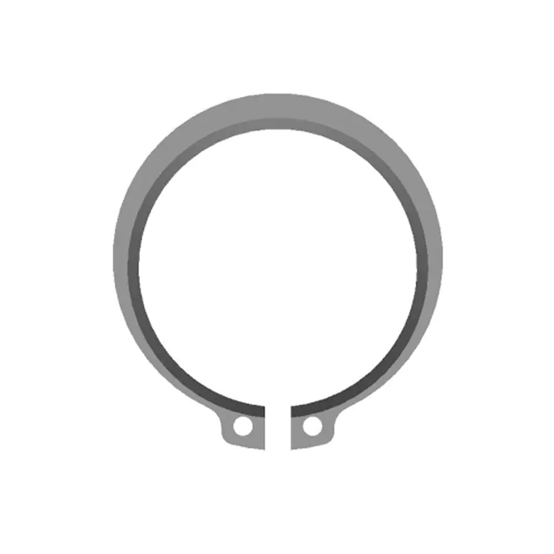
External retaining rings fit over the outside diameter of a shaft to position components like wheels, sprockets, or bearing races. During installation, the ring is expanded using pliers and then snaps into a pre-cut groove on the shaft exterior. These rings are subjected to tensile stresses during expansion and must possess sufficient ductility to avoid permanent deformation. External rings often have a larger cross-section compared to their internal counterparts to handle higher axial loads transmitted through rotating shafts. They are ubiquitous in automotive axles, electric motors, and conveyor systems where secure external retention is mandatory.
E-Clips and Push-On Rings for Rapid Assembly
E-clips represent a specialized subset of external retaining rings designed for applications where plier access is impossible or where rapid automated assembly is required. Shaped like the letter "E," these clips slide radially into the groove from the side rather than being expanded axially. They rely on three points of contact to grip the shaft securely and are ideal for low-to-medium load applications in consumer electronics, small appliances, and linkage mechanisms. Push-on rings, another variant, are pressed onto a shaft without grooves, relying solely on friction and biting teeth for retention, though they offer lower reusability compared to standard grooved retaining rings.
Precision Installation Protocols and Tooling Requirements
Proper installation of retaining rings is as critical as selection; improper handling can compromise the ring’s metallurgical structure and lead to field failures. Technicians must always use dedicated snap ring pliers matched to the ring size and lug configuration. Using improvised tools like screwdrivers or awls risks slipping, damaging the groove edges, or causing personal injury. For automated production lines, pneumatic or hydraulic installation tools ensure consistent seating force and cycle times, reducing variability and improving quality control metrics significantly.
Before installation, both the ring and the groove must be inspected for burrs, debris, or dimensional deviations. A damaged groove edge can act as a stress riser, leading to ring ejection under load. Lubrication is recommended during installation to reduce friction and prevent galling, especially for stainless steel rings which are prone to cold welding. After installation, it is imperative to verify that the ring is fully seated in the groove bottom by visual inspection or tactile verification. A partially seated ring will not achieve its rated thrust capacity and may rotate unexpectedly during operation, causing noise, wear, and eventual component displacement.
Load Capacity Analysis and Groove Design Standards
The functional limit of a retaining ring system is defined by two distinct failure modes: ring shear and groove deformation. Manufacturers provide rated thrust capacities based on standardized testing, but real-world applications require applying safety factors typically ranging from 2:1 for static loads to 4:1 for dynamic or shock-loaded assemblies. It is crucial to distinguish between the ring’s theoretical strength and the groove’s yield strength; often, the groove material fails before the ring itself shears. Engineers must calculate groove wall thickness and depth according to ANSI B27.7 or DIN 471/472 standards to ensure the substrate can support the intended axial force without plastic deformation.
Centrifugal force becomes a significant factor in high-speed rotating applications involving external retaining rings. As rotational speed increases, the outward radial force can overcome the ring’s grip on the groove, potentially causing it to expand and disengage. Specialized high-speed retaining rings with interlocking ends or self-locking features are available to counteract this effect. Additionally, sharp corners in groove design must be avoided; generous radii at the groove roots are essential to minimize stress concentration factors. Proper groove geometry ensures that the retaining ring functions as a reliable, predictable mechanical stop throughout the entire service life of the assembly.