


Content
- 1 What Are External Circlips With Lugs for Shafts — DIN 983?
- 2 How DIN 983 External Circlips Function as Axial Retainers
- 3 Correct Installation Procedure for DIN 983 External Circlips
- 4 DIN 983 Dimensional Specifications and Size Range
- 5 Material and Surface Treatment Options
- 6 Load Capacity and Engineering Considerations
- 7 Common Applications Across Industries
What Are External Circlips With Lugs for Shafts — DIN 983?
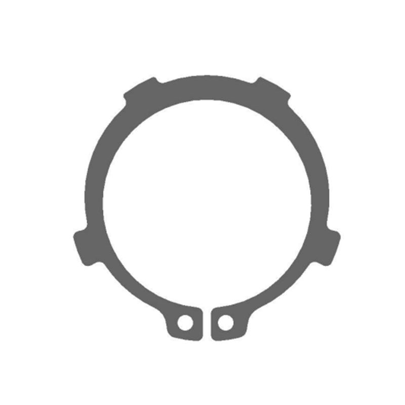
External circlips with lugs for shafts — DIN 983 are precision-engineered retaining rings designed to be installed on the outer surface of a grooved shaft to fix the axial movement of the parts mounted on it. As a standardized fastening component defined under the German DIN 983 specification, these circlips provide a reliable, compact, and cost-effective method of securing bearings, gears, pulleys, collars, and other rotating or sliding components against unintended lateral displacement along a shaft axis. They are widely used across automotive, industrial machinery, agricultural equipment, and consumer appliance manufacturing wherever robust axial retention is required without the added weight or complexity of threaded fasteners or shoulder machining.
The defining feature of the DIN 983 external circlip — as opposed to related standards such as DIN 471 — is the presence of lugs, also called ears or lug holes, on both ends of the open ring. These lugs are the engagement points for circlip pliers during installation and removal, giving the DIN 983 variant a practical advantage in confined assembly spaces where tool access is limited. The combination of a standardized groove geometry, consistent material specification, and well-defined lug design makes external circlips with lugs for shafts — DIN 983 one of the most dependable axial retention solutions available to design engineers and maintenance professionals alike.
How DIN 983 External Circlips Function as Axial Retainers
The operating principle of external circlips with lugs for shafts — DIN 983 is elegantly simple yet mechanically effective. The inner diameter of this type of retaining ring is slightly smaller than the diameter of the assembly shaft in its free, uninstalled state. This intentional interference means that once the circlip is expanded and seated into the pre-machined shaft groove, its natural spring-back force causes it to grip firmly within the groove walls, generating the radial clamping force that keeps it securely in place under axial loading.
When a component such as a bearing or gear is pressed onto the shaft and abuts the circlip's face, the circlip's bearing surface — the flat side wall of the ring that contacts the groove wall — transmits the axial load directly into the shaft. The groove geometry defined by DIN 983 is carefully proportioned to ensure that the groove walls carry the design load without yielding, while the circlip itself remains seated without being forced out radially under the axial thrust. This load path is entirely mechanical and requires no adhesives, welding, or secondary locking features, making DIN 983 circlips as easy to disassemble for maintenance as they are to install during initial assembly.
Correct Installation Procedure for DIN 983 External Circlips
Proper installation is critical to achieving the full axial retention capacity of external circlips with lugs for shafts — DIN 983. Because the inner diameter of the circlip is slightly smaller than the shaft diameter, the ring must be expanded beyond its free diameter before it can clear the shaft surface and drop into the groove. Attempting to force a DIN 983 circlip onto a shaft without the correct tool risks permanent deformation of the ring, which reduces its seating force and load-bearing capacity significantly.
When installing, you must use circlip pliers to insert the plier's mouth into the plier's hole of the retaining ring and expand the retaining ring before putting it into the pre-processed shaft groove. The correct tool for DIN 983 external circlips is an external circlip plier — a spring-loaded or compound-action plier with hardened tips sized to fit the lug holes precisely. Squeezing the plier handles spreads the tips outward, expanding the circlip's inner diameter sufficiently to slide over the shaft without scraping or gouging the shaft surface.
Step-by-Step Installation Guide
- Verify that the shaft groove dimensions match the DIN 983 specification for the selected circlip size — check groove diameter, groove width, and groove edge radii against the standard table before proceeding.
- Clean the shaft groove and the shaft surface to remove burrs, chips, scale, and any contamination that could prevent the circlip from seating fully or damage the ring during installation.
- Select the correct size of external circlip pliers with tip diameter matched to the DIN 983 lug hole size for the specific circlip being installed — using oversized tips risks enlarging the lug holes and weakening the ring.
- Insert the plier tips into the lug holes on both ends of the circlip simultaneously and squeeze the plier handles to expand the ring uniformly without twisting or bending it out of its flat plane.
- Position the expanded circlip over the shaft groove location and release pressure on the pliers gradually, allowing the circlip to contract into the groove under its own spring force.
- Confirm that the circlip is fully seated in the groove by checking that its entire circumference is visible within the groove and that no portion of the ring rides up onto the shaft diameter.
- Apply a light axial push force by hand to the retained component to verify that the circlip resists displacement — if the component moves axially, re-inspect the groove dimensions and circlip size selection.
DIN 983 Dimensional Specifications and Size Range
The DIN 983 standard defines a comprehensive range of external circlips with lugs for shafts covering shaft diameters from approximately 3 mm up to 300 mm, providing complete coverage for applications ranging from miniature precision instruments to large industrial gearboxes and heavy machinery shafts. Each size within the range specifies not only the circlip's free inner diameter and thickness but also the corresponding shaft groove dimensions — groove diameter, groove width, and allowable groove corner radius — that must be machined into the shaft to achieve a compliant installation.
| Shaft Diameter (mm) | Circlip Thickness (mm) | Groove Width (mm) | Groove Diameter (mm) |
| 10 | 1.0 | 1.1 | 9.3 |
| 20 | 1.2 | 1.3 | 18.5 |
| 30 | 1.5 | 1.6 | 27.9 |
| 50 | 2.0 | 2.15 | 46.8 |
| 80 | 2.5 | 2.65 | 74.5 |
| 100 | 3.0 | 3.15 | 93.5 |
It is important to note that groove dimensions are not identical to the nominal shaft diameter — the groove diameter is always smaller than the shaft diameter by an amount specified in the DIN 983 table for each size. Machining the groove to the correct diameter ensures that the circlip seats at the proper depth, maximizing the contact area between the ring and groove walls and achieving the rated axial load capacity. Oversized grooves reduce this contact area and lower the effective load capacity; undersized grooves may prevent the circlip from seating fully.
Material and Surface Treatment Options
The standard material specified for external circlips with lugs for shafts — DIN 983 is carbon spring steel, typically equivalent to grades such as C67S or 65Mn, which provides the combination of high yield strength, good fatigue resistance, and elastic springback needed for the ring to maintain its seating force throughout the service life of the assembly. The material is hardened and tempered after forming to achieve a hardness in the range of approximately 44 to 52 HRC, balancing hardness for load capacity with sufficient toughness to resist brittle fracture during installation expansion.
- Phosphate Coating: The most common standard surface treatment for DIN 983 circlips, providing a dark grey-black matte appearance with moderate corrosion protection and good oil retention for lubricated assemblies.
- Zinc Electroplating: Applied where enhanced corrosion resistance is required in moderately humid or mildly corrosive environments, typically with a clear or yellow chromate passivation layer over the zinc deposit.
- Stainless Steel (1.4310 / AISI 301): Available for DIN 983 circlips used in food processing, marine, pharmaceutical, or chemical applications where carbon steel corrosion is unacceptable — note that stainless variants have lower load capacity than hardened carbon steel rings of the same dimensions.
- Geomet or Dacromet Coating: Used in automotive and outdoor applications requiring superior salt-spray corrosion resistance without the hydrogen embrittlement risk associated with conventional electroplating of high-hardness spring steel.
Load Capacity and Engineering Considerations
The axial load capacity of external circlips with lugs for shafts — DIN 983 depends on several interrelated factors: the circlip material and hardness, the ring thickness, the groove geometry, the shaft material hardness, and the angle at which the axial load is applied relative to the circlip face. DIN 983 load capacity tables published by circlip manufacturers provide allowable axial thrust values for each standard size under the assumption that the groove is machined to the correct dimensions in a shaft of adequate hardness.
In practice, engineers must also consider dynamic loading conditions. Under oscillating or impact axial loads, the effective allowable load is reduced compared to the static capacity — typically by a dynamic load factor specified in the manufacturer's engineering data. For applications involving significant vibration, it is advisable to specify a circlip size one step larger than required by static load alone, or to use a locking compound applied to the groove to supplement the circlip's mechanical retention. Additionally, the groove edge sharpness matters considerably: a groove with an excessively large corner radius reduces the bearing area of the circlip and lowers the effective load capacity, making precise groove machining a non-negotiable requirement for reliable DIN 983 circlip performance.
Common Applications Across Industries
External circlips with lugs for shafts — DIN 983 are specified across an extraordinarily wide range of mechanical assemblies due to their combination of simplicity, standardization, and performance. In the automotive sector, they retain bearings and seals in gearbox shafts, differential assemblies, steering columns, and driveshaft components where reliable axial location under high dynamic loading is essential. In industrial machinery, they secure gears, sprockets, and coupling hubs on power transmission shafts in conveyor systems, pumps, compressors, and machine tools. Agricultural equipment relies on DIN 983 circlips extensively in combine harvesters, tractors, and tillage implements where the rings must perform reliably in dirty, vibration-rich environments.
Consumer appliances including washing machines, power tools, and electric motors also make extensive use of DIN 983 external circlips in their internal shaft and rotor assemblies, where the standardized sizing allows manufacturers to source components from multiple qualified suppliers without redesigning the shaft grooves. The universality of the DIN 983 standard across European and international manufacturing supply chains makes these external circlips with lugs for shafts one of the most procurement-friendly fastening components available — stocked by virtually every industrial fastener distributor worldwide in sizes spanning the full range from miniature precision shafts to large industrial driveshafts.


