


Content
- 1 Understanding External Circlip Size Definitions
- 2 Standard Shaft Groove Dimensions for External Circlips
- 3 Common International Standards for External Circlips
- 4 Typical Size Ranges and Dimensional Coverage
- 5 Tolerance Control and Fit Accuracy
- 6 Material Influence on Size Stability
- 7 Inspection and Measurement Practices
- 8 Selecting Sizes Based on Load and Application
Understanding External Circlip Size Definitions
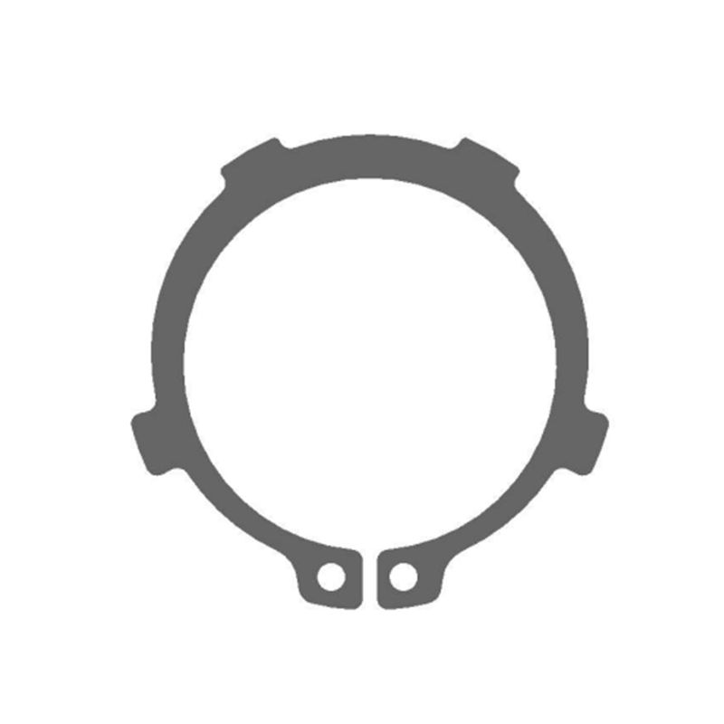
External circlip sizes are primarily defined by the nominal shaft diameter they are designed to fit. Unlike internal circlips, which seat inside a bore, external circlips are installed onto a machined groove on a shaft. The stated size corresponds to the shaft diameter rather than the outer diameter of the circlip itself. This distinction is critical during specification, as selecting based on circlip outer diameter can lead to incorrect groove engagement and reduced axial retention performance.
In addition to nominal shaft diameter, size definitions also account for circlip thickness, free diameter, and installed diameter. These dimensional relationships determine how the circlip expands during installation and how securely it sits within the shaft groove once released.
Standard Shaft Groove Dimensions for External Circlips
Proper groove geometry is essential for external circlip function. Standards specify groove width, groove diameter, and allowable corner radii to ensure the circlip seats fully and distributes load evenly. Deviations from these values can cause uneven stress, premature wear, or circlip displacement under axial load.
Groove depth must allow the circlip to sit flush without excessive protrusion, while still maintaining sufficient interference to resist axial movement. Shaft grooves that are too shallow can prevent full circlip seating, whereas overly deep grooves reduce effective retention.
Common International Standards for External Circlips
External circlips are governed by several widely recognized standards that ensure dimensional consistency and interchangeability across manufacturers. The most commonly referenced standards define size ranges, tolerances, material conditions, and test requirements.
- DIN 471, widely used in Europe for standard external circlips on shafts
- ISO 8752 and related ISO specifications for metric circlip dimensions
- ASME and ANSI references for inch-based snap rings in North American markets
When sourcing external circlips for global equipment or OEM supply chains, aligning part selection with the applicable standard helps reduce compatibility issues during assembly and maintenance.
Typical Size Ranges and Dimensional Coverage
Standard external circlips are available across a broad range of shaft diameters, supporting both small precision assemblies and large mechanical systems. Metric sizes typically start from small shaft diameters used in instruments and extend to large diameters found in industrial machinery and drive systems.
| Size Category | Typical Shaft Diameter Range | Common Applications |
| Small | 3 mm to 12 mm | Motors, instruments, compact gearboxes |
| Medium | 15 mm to 60 mm | Automotive components, industrial machinery |
| Large | 65 mm and above | Heavy equipment, power transmission shafts |
Tolerance Control and Fit Accuracy
Tolerance control plays a direct role in the reliability of external circlips. Standards specify tolerances for circlip thickness, free diameter, and lug dimensions to balance ease of installation with secure groove engagement. Excessively tight tolerances may complicate assembly, while loose tolerances increase the risk of axial movement.
Shaft groove tolerances are equally important. Consistency between groove diameter and circlip installed diameter determines the residual clamping force that holds the circlip in place during operation.
Material Influence on Size Stability
Material selection affects how closely external circlips maintain their nominal dimensions under load and environmental exposure. Spring steel is commonly used due to its elastic recovery, allowing the circlip to expand during installation and return to its designed working diameter.
For corrosive environments, stainless steel variants may be used, though differences in modulus and spring characteristics can influence effective tolerances. Material properties should be considered alongside size specifications when evaluating long-term performance.
Inspection and Measurement Practices
Accurate inspection helps verify that external circlips meet size and tolerance requirements before installation. Common measurement practices include checking thickness with micrometers, verifying free diameter, and inspecting lug symmetry. These checks help identify deformation caused by improper handling or previous use.
During maintenance, worn or permanently deformed circlips should be replaced rather than reused, as dimensional changes can compromise axial retention even if the nominal size appears correct.
Selecting Sizes Based on Load and Application
While size standards define dimensional compatibility, application requirements determine whether a given size is suitable for the expected axial loads. Higher loads may require selecting a larger shaft diameter or a circlip with greater thickness within the same nominal size range.
Considering shaft material, groove finish, and operating conditions alongside size and tolerance data leads to more reliable external circlip performance in real-world assemblies.


