


Content
- 1 What Are External Circlips and How Do They Work
- 2 Key Differences Between External and Internal Retaining Rings
- 3 Correct Installation Procedure for External Retaining Rings
- 4 Materials and Surface Treatments for Different Service Conditions
- 5 Sizing External Circlips: Key Parameters and Standards
- 6 Common Failure Modes and How to Avoid Them
What Are External Circlips and How Do They Work
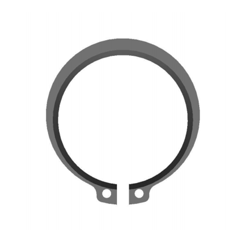
External circlips — also referred to as external retaining rings — are open-ended, spring-steel fasteners designed to seat into a machined groove on the outer diameter of a shaft. Once installed, they present a rigid shoulder that prevents mounted components such as bearings, gears, pulleys, and collars from moving axially along the shaft. This axial retention function is deceptively simple in concept but critical in practice: without a reliable retaining feature, components subject to thrust loads, vibration, or rotational forces will migrate along the shaft, causing misalignment, accelerated wear, and eventual mechanical failure.
The working principle relies on the geometry of the ring relative to the shaft. The inner diameter of the external circlip is slightly smaller than the diameter of the assembly shaft. In its free state, the ring sits in compression against the shaft groove walls. When a component bears against the ring's face, the compressive preload prevents the ring from rotating or popping out of the groove under normal operating loads. This interference-fit relationship between ring and groove is what gives external retaining rings their load-bearing capability without requiring threads, welding, or additional fasteners.
The external circlip is one of the most widely used retaining methods in mechanical engineering precisely because it combines minimal radial envelope, low component count, and fast assembly — all without permanently altering the shaft. A correctly specified and installed external retaining ring adds negligible weight and complexity to an assembly while providing axial retention forces that can reach several kilonewtons depending on ring size and groove design.
Key Differences Between External and Internal Retaining Rings
Understanding where external circlips fit within the broader retaining ring family helps engineers select the right component for each application. The primary distinction lies in the mounting surface: external retaining rings install on shafts, while internal retaining rings install inside bores. The mechanical logic is reversed — external rings are compressed for installation, internal rings are expanded.
The table below summarizes the key differences between the two ring types across the criteria most relevant to selection and application:
| Attribute | External Circlips | Internal Retaining Rings |
|---|---|---|
| Mounting Surface | Outer diameter of shaft | Inner diameter of bore or housing |
| Installation Action | Expanded outward to fit over shaft | Compressed inward to fit into bore |
| Tool Required | External circlip pliers (spreading tips) | Internal circlip pliers (closing tips) |
| Free-State Ring ID | Smaller than shaft diameter | Larger than bore diameter |
| Typical Applications | Bearing retention on shafts, gear axles | Bearing retention in housings, cylinders |
In assemblies that retain a bearing between a shaft and a housing simultaneously, both ring types are often used together — the external retaining ring locks the bearing on the shaft, and an internal ring locks it within the housing bore. Misidentifying ring type during replacement is a common maintenance error that leads to incorrect tool selection, installation difficulty, and potential ring failure.
Correct Installation Procedure for External Retaining Rings
Proper installation is the single most important factor in external circlip performance. A correctly specified ring installed incorrectly will fail at a fraction of its rated load capacity — and in rotating machinery, an ejected retaining ring can cause cascading component failures and serious safety hazards. The installation process must follow a defined sequence to ensure the ring seats fully and evenly in the groove.
Step 1 — Verify Groove and Ring Dimensions
Before installation, confirm that the shaft groove has been machined to the dimensions specified for the ring size in use. Groove width, groove depth, and groove edge radius all affect how completely the ring seats and how much of the ring cross-section projects above the shaft to form the retaining shoulder. An undersized groove depth prevents full ring seating; an oversized groove width allows the ring to tilt under load and reduces its effective thrust capacity.
Step 2 — Select and Use Correct Circlip Pliers
When installing external circlips, you must use circlip pliers specifically designed for external ring installation. The procedure requires inserting the plier's mouth into the plier's hole — the small circular holes stamped at each end of the retaining ring — and then squeezing the plier handles to expand the retaining ring diameter. This expansion increases the ring's inner diameter sufficiently to pass over the shaft diameter and slide along the shaft to the groove location. Using improvised tools such as screwdrivers or needle-nose pliers risks overstressing the ring, scratching the shaft, and creating a non-uniform expansion that leaves the ring partially unseated.
Step 3 — Seat the Ring Fully in the Groove
With the ring expanded, position it directly over the groove location and release the plier tension gradually, allowing the ring to contract into the groove under its own spring force. After releasing the pliers, visually and tactilely verify that the entire ring circumference sits flush within the groove with no section bridging the groove edges. A correctly seated external retaining ring will have both lugs — the ends of the ring — at equal height above the shaft surface and the ring body fully recessed in the groove with the retaining shoulder projecting evenly on all sides.
Step 4 — Check Axial Play and Ring Security
After installation, attempt to rotate the ring within the groove by hand. A correctly installed external circlip should rotate freely in the groove but should not move axially or tilt noticeably when axial force is applied to the retained component. Any wobble, tilt, or partial ejection from the groove indicates an installation error or dimensional mismatch that must be resolved before the assembly is put into service.
Materials and Surface Treatments for Different Service Conditions
The material specification of external circlips directly determines their performance in terms of static thrust capacity, fatigue resistance, corrosion behavior, and temperature tolerance. Standard external retaining rings are produced from carbon spring steel — typically 65Mn or equivalent — which provides the high yield strength and elastic recovery needed for repeated installation and removal cycles. However, the full range of service environments encountered in industrial applications requires a broader material palette.
- Carbon spring steel (65Mn / SAE 1060–1090) — the standard material for general industrial use; high yield strength supports good thrust capacity; susceptible to corrosion in humid or chemically aggressive environments without surface treatment
- Stainless steel (AISI 301 / 420) — selected for applications involving moisture, mild acids, food contact, or outdoor exposure; lower yield strength than carbon steel reduces maximum thrust rating by approximately 20–30%, which must be factored into the design safety margin
- Beryllium copper — non-magnetic and non-sparking; used in explosive atmospheres, strong magnetic fields, and precision electronics where steel rings would cause interference or ignition risk
- Phosphate and oil treatment — the most common surface treatment for carbon steel external circlips; provides moderate corrosion resistance for indoor applications and reduces galling during installation and removal
- Zinc plating and passivation — improves corrosion resistance substantially over phosphated rings; suitable for applications with intermittent moisture exposure; may require hydrogen embrittlement relief treatment for high-strength ring grades
- Dacromet or geomet coating — used where high corrosion resistance combined with low coating thickness is required; commonly specified for automotive and outdoor power equipment applications
Sizing External Circlips: Key Parameters and Standards
External circlips are standardized components dimensioned primarily by the shaft diameter they are designed to fit. International standards including DIN 471, ISO 7430, and ANSI/ASME B18.27.1 define the ring dimensions, groove dimensions, and thrust ratings for each shaft size. Working within these standards ensures dimensional interchangeability and allows engineers to reference published load capacity data when verifying that a selected ring meets the axial force requirements of the application.
The principal dimensional parameters that define an external retaining ring for a given shaft size are:
- Shaft diameter (d) — the nominal outer diameter of the shaft at the groove location; this is the primary selection parameter from which all other ring and groove dimensions derive
- Ring inner diameter (d1) — the free-state inner diameter of the ring, which is smaller than the shaft diameter to ensure the ring grips the groove; the difference between d1 and d determines the spring preload holding the ring in position
- Ring thickness (s) — the axial width of the ring cross-section; thicker rings resist higher thrust loads but require wider grooves that reduce shaft cross-sectional area
- Ring radial width (b) — the projecting shoulder height above the shaft groove; this dimension determines how much bearing surface the ring presents to the retained component and directly affects allowable thrust load
- Maximum allowable thrust load (Fa) — published by ring manufacturers and standards bodies for each shaft diameter and material grade; the design thrust load applied by the retained assembly must not exceed this value with appropriate safety factors applied
For shaft diameters ranging from 3 mm to over 300 mm, standardized external circlips and external retaining rings are available from stock. Custom ring profiles — modified thickness, alternative lug geometry, or non-standard inner diameters — can be produced for high-volume applications where the standard geometry does not meet specific space or load requirements, though custom rings require bespoke groove machining specifications to match.
Common Failure Modes and How to Avoid Them
External circlips are reliable components, but they fail when overloaded, incorrectly installed, or used outside their specified operating conditions. Recognizing the characteristic failure modes enables engineers and maintenance technicians to identify root causes quickly and implement corrective measures before repeated failures become a chronic reliability problem.
- Ring ejection from groove — most commonly caused by thrust loads exceeding the ring's rated capacity, or by a groove depth that is too shallow to retain the ring under load; verify groove dimensions and recalculate thrust load against ring rating with safety factor
- Ring fracture during installation — results from over-expansion beyond the manufacturer's stated maximum expansion limit, or from using pliers that apply uneven force; replace with a correctly sized ring and use pliers with tips that fit the plier holes precisely
- Fatigue cracking under cyclic load — occurs when dynamic thrust loads cause repeated stress cycling in the ring cross-section; address by upgrading to a heavier-section ring, switching to a higher-strength material grade, or adding a thrust washer between the retained component and the ring to distribute contact stress
- Corrosion-induced groove seizure — in humid or chemically aggressive environments, rust buildup in the groove can lock the ring in place, making removal difficult and damaging the shaft groove; prevent with appropriate ring material selection and periodic inspection with lubrication in accessible assemblies
- Partial seating due to groove burrs — machining burrs at the groove edges prevent the ring from fully entering the groove, leaving it partially proud of the shaft surface and reducing its effective thrust shoulder; deburr grooves thoroughly before ring installation as a standard procedure
With correct groove machining, proper tool use, and material selection matched to the operating environment, external circlips and external retaining rings consistently deliver long service lives with zero maintenance requirements — making them one of the most cost-effective axial retention solutions available across the full breadth of mechanical engineering applications.


