


Content
- 1 What an Internal Circlip Does — and Why Correct Installation Matters
- 2 Choosing the Right Circlip Pliers for Bore Installation
- 3 How to Install an Internal Circlip: Step-by-Step
- 4 How to Remove an Internal Circlip Safely
- 5 5 Common Internal Circlip Installation Mistakes — and How to Avoid Them
- 6 Material Grade and Circlip Quality: Why It Affects Axial Retention
What an Internal Circlip Does — and Why Correct Installation Matters
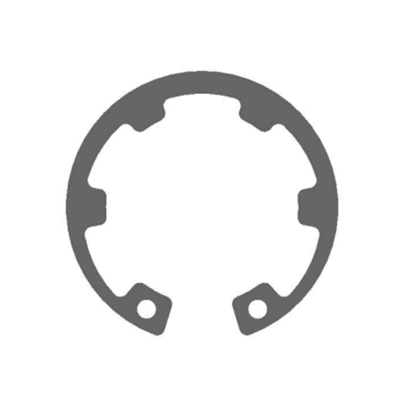
An internal circlip is a spring-steel retaining ring installed inside a bore to prevent the axial movement of components housed within that bore. Once seated in a machined groove, the circlip's natural elasticity causes it to expand outward against the groove walls, creating a mechanical shoulder that holds bearings, pins, shafts, and other parts firmly in position along the axis.
The outer diameter of an internal circlip is slightly larger than the bore diameter it is designed for. This dimensional relationship is what generates the retention force — when the circlip is compressed during installation and then released into the groove, it springs back toward its original diameter, locking itself into position. The result is a compact, tool-free fastening solution that requires no threads, no adhesive, and no welding.
What makes installation technique so critical is the consequence of getting it wrong. A circlip that is not fully seated in its groove can migrate under load, allowing the retained component to shift axially. In a bearing application, this produces misalignment and accelerated wear. In a hydraulic or pneumatic assembly, it can cause seal failure. In high-speed rotating equipment, an unseated internal circlip for bore applications is a potential safety hazard. Understanding the correct process — from tool selection through to post-installation verification — eliminates these risks before they reach the finished assembly.
Choosing the Right Circlip Pliers for Bore Installation
The single most important tool decision in internal circlip installation is selecting the correct type of circlip pliers. Using the wrong pliers — or improvising with general-purpose tools — is the most common starting point for installation problems.
Internal vs. external circlip pliers. Internal and external circlips require opposite plier actions. Internal circlip pliers compress the ring when the handles are squeezed — this reduces the circlip's diameter so it can be inserted into the bore. External circlip pliers expand the ring when squeezed, which is the reverse action needed for shaft-mounted rings. Using external pliers on an internal circlip will expand the ring rather than compress it, making installation impossible and potentially damaging the circlip. Always confirm plier type before beginning. For external applications, refer to external circlips for shaft retention, which require a different plier configuration entirely.
Straight-nose vs. bent-nose pliers. Straight-nose internal circlip pliers work well when the bore is accessible from directly in front and there is sufficient clearance around the opening. Bent-nose pliers — typically available at 45-degree or 90-degree angles — are necessary when the bore is recessed, oriented at an angle, or surrounded by adjacent components that block straight access. Having both configurations available prevents the need to force a straight-nose plier into an awkward position, which reduces control and increases the risk of the circlip slipping during compression.
Tip size and circlip hole matching. Circlip plier tips must fit the lug holes at the ends of the circlip accurately. Tips that are too large cannot enter the holes fully, which means the pliers are not properly engaged with the ring — the circlip can slip off the plier tips under compression, often launching the ring unpredictably. Tips that are too small enter the holes but do not provide full engagement, creating the same slipping risk. Many professional-grade circlip pliers include interchangeable tips in multiple diameters. Match tip diameter to the circlip's lug hole diameter before compressing.
Plier size relative to circlip diameter. Pliers should be appropriately sized for the circlip being installed. Undersized pliers may lack the leverage to compress a large-diameter circlip fully. Oversized pliers are difficult to maneuver in confined bores and reduce tactile feedback during installation. As a general guideline, the plier jaw span when open should comfortably accommodate the circlip diameter without requiring the handles to be forced to their stop position just to engage the lug holes.
How to Install an Internal Circlip: Step-by-Step
With the correct pliers selected and sized, installation follows a consistent sequence. Each step serves a specific purpose — skipping any of them increases the probability of an incorrectly seated circlip reaching the finished assembly.
- Inspect the circlip before installation. Check the ring for deformation, corrosion, nicks, or any sign of previous use damage. A circlip that has been over-compressed before, visibly bent, or shows surface corrosion at the lug holes should be discarded. The cost of a replacement circlip is negligible compared to the cost of a field failure.
- Clean and inspect the bore groove. Wipe the groove and bore interior with a clean cloth. Remove any burrs, metallic debris, or contamination from the groove channel. Debris in the groove prevents the circlip from seating fully and evenly. Confirm the groove dimensions are within specification — a worn or oversized groove will not retain the circlip under load regardless of how well the installation is performed.
- Apply a light lubricant if required. In some applications, a small amount of clean oil or assembly lubricant on the circlip and bore entry edge makes insertion smoother, particularly for larger-diameter rings that require significant compression. Do not use grease or heavy lubricants that could contaminate adjacent components such as dry bearings or friction surfaces.
- Engage the circlip plier tips in the lug holes fully. Insert both plier tips completely into the circlip's lug holes. Partial engagement is a primary cause of the circlip slipping off the pliers during compression. Confirm both tips are seated before applying any compressive force.
- Compress the circlip and guide it into the bore. Squeeze the plier handles steadily to compress the ring until its outer diameter is slightly smaller than the bore diameter. Keep compression to the minimum needed for insertion — excessive compression beyond what is required weakens the spring temper of the ring. With the ring compressed, align it with the bore axis and guide it inward to the groove position. Keep the ring perpendicular to the bore axis throughout this movement to ensure it enters the groove evenly.
- Release and verify full seating. Once the circlip is positioned at the groove, release the plier handles gradually. The ring will expand outward into the groove under its own spring force. Remove the pliers, then use a flat probe or pick to press around the full circumference of the circlip, confirming that it is seated uniformly in the groove with no section raised above the groove edge. A correctly installed internal circlip should not move when pressed with moderate finger force.
How to Remove an Internal Circlip Safely
Circlip removal follows the reverse sequence of installation, with one additional consideration: a circlip under compression can be released unpredictably if plier engagement is lost, and the released ring can travel at significant velocity. Eye protection is not optional when removing circlips.
Re-engage the internal circlip plier tips fully into the lug holes. Squeeze the handles to compress the ring inward, reducing its diameter below the bore's inner wall. With the ring compressed, slide it axially out of the groove and withdraw it from the bore. Release the handles only after the ring is clear of the bore entirely.
If the lug holes are corroded, filled with debris, or otherwise inaccessible, clean them with a fine pick before attempting plier engagement. Attempting to lever a circlip out of its groove with a screwdriver or flat tool without compressing it first risks damaging the groove, the adjacent component, or the circlip itself — and creates an uncontrolled release risk.
Assess the removed circlip before considering reuse. If the ring shows any permanent deformation, has lost its spring tension (it should feel resistant when compressed by hand), or shows corrosion at the lug holes or along the body, replace it. A circlip that has been in service for an extended period in a high-load or high-temperature application should generally be replaced as a matter of routine rather than reused.
5 Common Internal Circlip Installation Mistakes — and How to Avoid Them
Most internal circlip failures in service are traceable to installation errors rather than material or design deficiencies. The following five mistakes account for the majority of field problems.
1. Using the wrong circlip size. An internal circlip must match the bore diameter precisely. A ring that is too small will not exert sufficient radial force against the groove walls and can migrate or eject under axial load. A ring that is too large cannot be compressed sufficiently to enter the bore without exceeding its elastic limit — and if forced, it will be permanently deformed before it is even installed. Always verify the bore diameter and select the circlip size accordingly. For standard bore sizes, circlip manufacturers publish dimension tables that specify the correct ring size for each bore diameter.
2. Over-compressing the circlip during installation. Compressing a circlip beyond its design limit permanently reduces its spring force. The ring may appear to seat correctly but will have reduced retention capacity in service. This is particularly common when installers use pliers that are too large for the application, generating more leverage than necessary. Compress only enough to clear the bore diameter — once the ring enters the groove, the spring force required for retention is generated by the release from compression, not by additional force applied after seating.
3. Failing to verify full groove seating. A circlip can appear seated from one angle while one section remains partially raised above the groove. This is most common in deep or blind bores where visual access is limited. The consequence is a circlip that holds initially but fails when the axial load reaches the partially unseated section. After every installation, probe the full circumference of the ring with a pick or fine rod to confirm uniform seating before closing the assembly.
4. Reusing a visibly worn or previously over-compressed circlip. A circlip that has been removed from service and shows any deformation, corrosion, or reduced spring tension should not be reinstalled. The spring properties of the ring material are essential to its retention function — a ring that has lost those properties through fatigue, corrosion, or over-compression will not perform reliably even if it appears to seat correctly. Circlips are low-cost components relative to the assemblies they protect. Replace them.
5. Installing without eye protection. A circlip under compression that slips from the plier tips releases its stored elastic energy immediately and unpredictably. This is not a rare occurrence — it happens to experienced technicians when plier tips are worn, lug holes are corroded, or grip is lost for any reason. Safety glasses or a face shield should be worn for every internal circlip installation and removal operation, regardless of how routine the task appears.
Material Grade and Circlip Quality: Why It Affects Axial Retention
The installation technique described above assumes that the circlip being installed has the correct mechanical properties for the application. Material grade is not a detail that can be compensated for by careful installation — a circlip made from substandard or incorrectly processed material will fail in service regardless of how precisely it is seated.
Standard internal circlips are produced from carbon spring steel, typically 65Mn or equivalent grades, which offer the combination of high yield strength and sufficient elongation to survive repeated compression without permanent deformation. The material must be correctly heat-treated — hardened and tempered to a defined hardness range — to achieve the spring properties that make retention reliable under sustained axial load.
For applications involving moisture exposure, corrosive media, or food-contact environments, stainless steel circlips are the appropriate choice. Grades such as 304 and 316 stainless provide corrosion resistance that carbon steel cannot match, though with slightly different spring characteristics that should be accounted for in the groove design. The selection between carbon steel and stainless should be made at the specification stage, not as a field substitution.
Dimensional consistency across production batches matters for high-volume assembly operations. Circlips that vary in thickness, lug hole diameter, or outer diameter from batch to batch create inconsistent retention forces and increase the probability of installation problems. Manufacturers operating under ISO9001 quality systems with in-process dimensional inspection provide the batch consistency that production assembly environments require.
Anhui Ningguo Dongbo Fastener specialises in the manufacture of internal circlips, external circlips, and snap rings in standard and custom sizes, produced from carbon spring steel and stainless steel to DIN, ANSI, and JIS standards. With dedicated stamping and heat-treatment lines and full quality control documentation, Dongbo supplies retaining rings to industrial, automotive, and engineering customers worldwide. Contact the team for specification assistance or to request samples for qualification testing.


