English
 中文简体
中文简体
Content
- 1 What Internal Circlips Are and How They Retain Components in Bores
- 2 Spring Steel Internal Circlip: Material Properties and Why They Matter
- 3 Internal Circlips vs External Circlips: Fundamental Differences and Selection Logic
- 4 Groove Design and Dimensional Specifications for Internal Circlips
- 5 Common Installation Errors and How to Avoid Them
What Internal Circlips Are and How They Retain Components in Bores
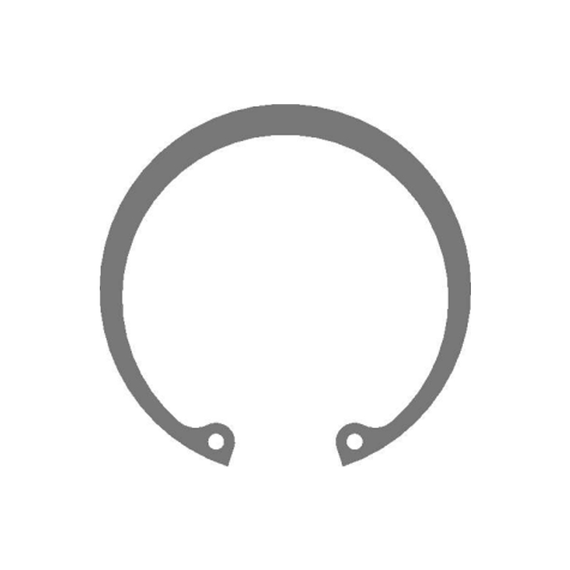
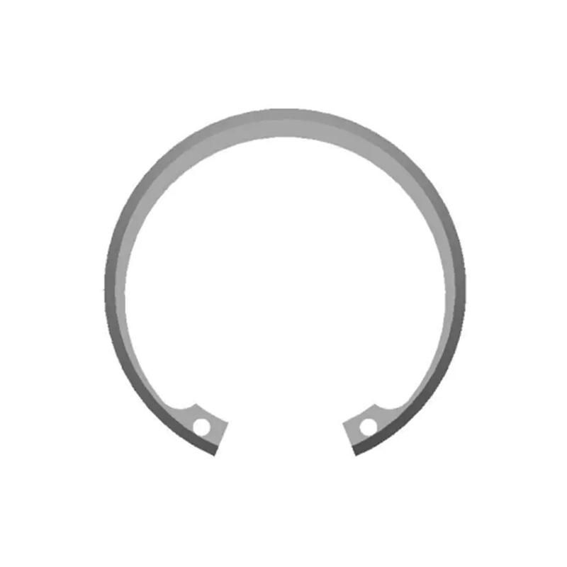
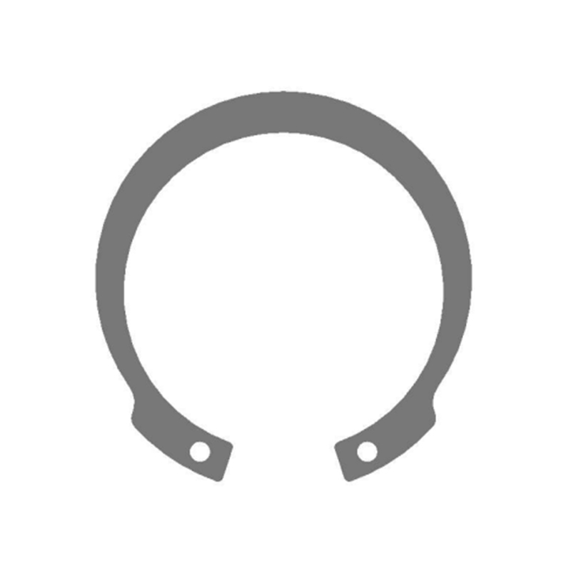
Internal circlips are open-ended retaining rings designed to be installed inside a cylindrical bore or housing, where they sit in a machined groove and prevent axial movement of shafts, bearings, pins, or other components seated within that bore. The defining geometric characteristic of an internal circlip is that its outer diameter in the free, uninstalled state is slightly larger than the bore diameter it is designed to fit. This deliberate interference is what generates the radial clamping force that holds the ring securely in its groove once installed — no adhesive, thread, or fastener is involved. The retaining force is entirely mechanical, derived from the elastic recovery of the ring material after compression during installation.
The installation sequence for internal circlips is precise and must be followed correctly to achieve reliable retention. Internal circlip pliers are inserted into the two small holes punched into the ears of the ring — one plier jaw into each hole. The pliers are squeezed, which compresses the ring and reduces its outer diameter below the bore diameter, allowing the ring to be positioned concentrically over the groove opening inside the bore. Once aligned with the groove, the pliers are released. The elastic recovery of the ring material causes it to expand outward, driving the ring body into the groove walls and creating a tight, gap-free fit around the full circumference of the groove. The ring is now locked in place and resists axial loads applied from either direction against its flat face.
The axial load capacity of an installed internal circlip depends on three variables: the shear strength of the ring material, the cross-sectional area of the ring where it contacts the groove wall, and the groove geometry itself. A correctly dimensioned groove — with width matched to the ring thickness and depth matched to the ring's radial width — distributes the load evenly across the full ring circumference. An undercut or oversized groove concentrates stress at discrete points and dramatically reduces the effective load rating of the assembly, sometimes to the point of ring ejection under normal service loads.
Spring Steel Internal Circlip: Material Properties and Why They Matter
The overwhelming majority of internal circlips in general industrial service are manufactured from spring steel — specifically high-carbon spring steel conforming to standards such as DIN 17222, EN 10132-4, or equivalent national specifications. The carbon content of spring steel used for circlips typically falls in the range of 0.65–0.85% carbon, with manganese, silicon, and chromium additions depending on the grade. This composition, combined with a controlled quench-and-temper heat treatment after forming, produces a material with the specific combination of properties that circlip function demands.
Key Mechanical Properties of Spring Steel for Circlips
The performance of a spring steel internal circlip in service depends on the following material characteristics being within specification:
- High yield strength (800–1,200 MPa typical): The ring must resist permanent deformation when compressed during installation and when loaded axially in service. A ring that yields during compression takes a set and cannot recover to its original diameter, resulting in a loose fit in the groove and unreliable retention.
- Controlled elasticity (modulus of elasticity ~200 GPa): The ring must recover fully and predictably to its free diameter after the installation compression force is released. The magnitude of this recovery determines the contact pressure between the ring and the groove walls, which directly sets the retention force.
- Adequate toughness and ductility: Despite the high hardness required for spring function, the material must resist brittle fracture during the compression-expansion cycle of installation. Circlips that shatter rather than deflect during plier compression are a significant safety hazard and indicate either material deficiency or incorrect installation tooling.
- Surface finish and edge condition: Stamped circlips have a sheared edge on the inner and outer diameters. Burrs or micro-cracks at the shear edge act as stress concentrators under repeated loading. High-quality spring steel internal circlip production includes a deburring or edge-conditioning step after stamping to eliminate these defects.
For applications involving exposure to moisture, salt spray, or mild chemical environments, spring steel circlips are typically phosphated or zinc-plated after heat treatment to provide corrosion resistance without altering the mechanical properties of the spring steel substrate. Where corrosion resistance must be intrinsic rather than coating-dependent — as in food processing, marine, or pharmaceutical applications — stainless steel grades such as 1.4310 (AISI 301) are used instead, with a corresponding reduction in achievable spring force due to the lower yield strength of austenitic stainless steel compared to hardened carbon spring steel.
Internal Circlips vs External Circlips: Fundamental Differences and Selection Logic
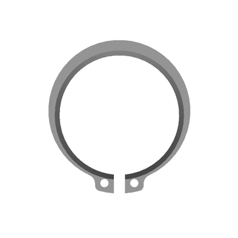
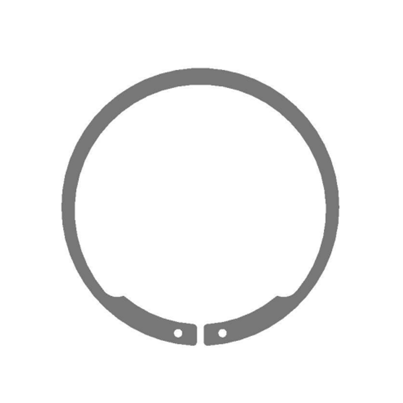
External circlips perform the same axial retention function as internal circlips, but they operate in the opposite geometric context: they are installed in a groove machined into the outer diameter of a shaft or pin, rather than into the inner surface of a bore. Where internal circlips compress to install and then expand into their groove, external circlips must be expanded during installation — using external circlip pliers that spread the ring open — and then contract onto the shaft groove when the pliers are released.
| Feature | Internal Circlips | External Circlips |
|---|---|---|
| Installation location | Inside a bore or housing groove | Outside a shaft or pin groove |
| Installation action | Compressed to reduce OD, then released | Expanded to increase ID, then released |
| Plier type required | Internal (closing) circlip pliers | External (opening) circlip pliers |
| Free diameter vs. groove | OD slightly larger than bore | ID slightly smaller than shaft |
| Standard reference | DIN 472 / ISO 9626 | DIN 471 / ISO 9626 |
| Typical applications | Gearboxes, pump housings, engine bores | Motor shafts, axles, pulley assemblies |
| Axial load direction | Retains component pushed into bore | Retains component pushed along shaft |
The selection between internal circlips and external circlips is determined entirely by where the retaining groove is located in the assembly. If the component to be retained is seated inside a bore — a bearing pressed into a housing, a bush in a hydraulic cylinder, a seal in an engine block — an internal circlip is required. If the component slides onto a shaft and must be prevented from moving along that shaft — a gear on a gearbox output shaft, a pulley on a motor shaft, a wheel hub on an axle — an external circlip is the correct choice. Using the wrong type is not a minor deviation: the groove geometries are different, the plier actions are opposite, and fitting an external circlip into an internal groove or vice versa will result in a retention assembly that is either impossible to seat correctly or fails immediately under load.
Groove Design and Dimensional Specifications for Internal Circlips
The groove into which an internal circlip is installed is as critical to the assembly's performance as the circlip itself. A groove that is too wide allows the ring to rock under load, reducing the effective contact area and increasing the risk of ring ejection. A groove that is too narrow prevents full seating of the ring, leaving part of the ring cross-section proud of the groove and reducing the axial load capacity proportionally. The following dimensional parameters must be controlled when machining grooves for internal circlips:
- Groove width (b): Should match the circlip thickness with a tolerance of +0.05 to +0.15 mm for standard DIN 472 rings. Wider tolerances are acceptable only where dynamic loading is absent and the retention function is purely positional.
- Groove depth (t): Must allow the ring to seat fully below the bore surface so that the retained component contacts the ring face rather than riding over it. For DIN 472 rings, groove depth is typically 1.1 to 1.3 times the radial width of the ring section.
- Groove corner radius: A sharp corner at the groove root creates a stress concentration in the housing material. A radius of 0.1 to 0.3 mm at the groove root distributes the load more evenly and reduces the risk of fatigue cracking in the housing under cyclic axial loading.
- Surface finish of the groove walls: A roughness of Ra 1.6 µm or better on the groove side walls maximizes the contact area between the ring and the groove, improving load transfer and minimizing fretting wear in dynamic applications.
Common Installation Errors and How to Avoid Them
The simplicity of circlip installation makes it easy to overlook critical details that determine whether the retention assembly will perform reliably over its intended service life. The following errors account for the majority of premature internal circlip failures in service:
- Over-compression during installation: Compressing the ring beyond the minimum diameter required to clear the bore damages the spring steel microstructure at the ear region, reducing the elastic recovery force and producing a ring that seats loosely in the groove. Always use pliers with correctly sized tips that engage the plier holes without imposing additional bending loads on the ring body.
- Misalignment during seating: Releasing the pliers before the ring is fully aligned with the groove causes the ring to seat partially, with one side in the groove and the other riding on the bore surface. The result is a ring that appears installed but ejects under the first axial load. Always confirm the ring is visually flush with the groove opening before releasing plier pressure.
- Reusing removed circlips: A spring steel internal circlip that has been compressed for installation and then removed has experienced one elastic strain cycle. Reinstalling the same ring imposes a second cycle, and if the ring was over-compressed during the first installation, its free diameter will have changed. Always use new circlips when reassembling after maintenance.
- Incorrect plier tip size: Plier tips that are too small for the ring's plier holes bear on the edge of the hole rather than distributing load across its full diameter, creating a lever action that tilts the ring during compression. Use a circlip plier set with matched tip sizes for each circlip diameter range rather than a single fixed-tip tool for all sizes.
- Installing in a dry, contaminated, or corroded groove: Light oil applied to the ring and groove before installation reduces the friction during seating and allows the ring to align itself more evenly in the groove as it expands. Corroded or contaminated grooves must be cleaned to the base metal before installation to ensure full ring contact with the groove walls.
When external circlips and internal circlips are both used in the same assembly — as is common in gearbox and transmission design where shaft-mounted and housing-mounted retention rings are combined — maintaining a clear identification and storage system for the two types prevents installation errors. Despite their similar appearance when out of context, the two ring types are not interchangeable, and cross-installation creates a retention failure that is often difficult to diagnose without full disassembly of the affected component.