Content
Understanding the Core Function of Snap Rings
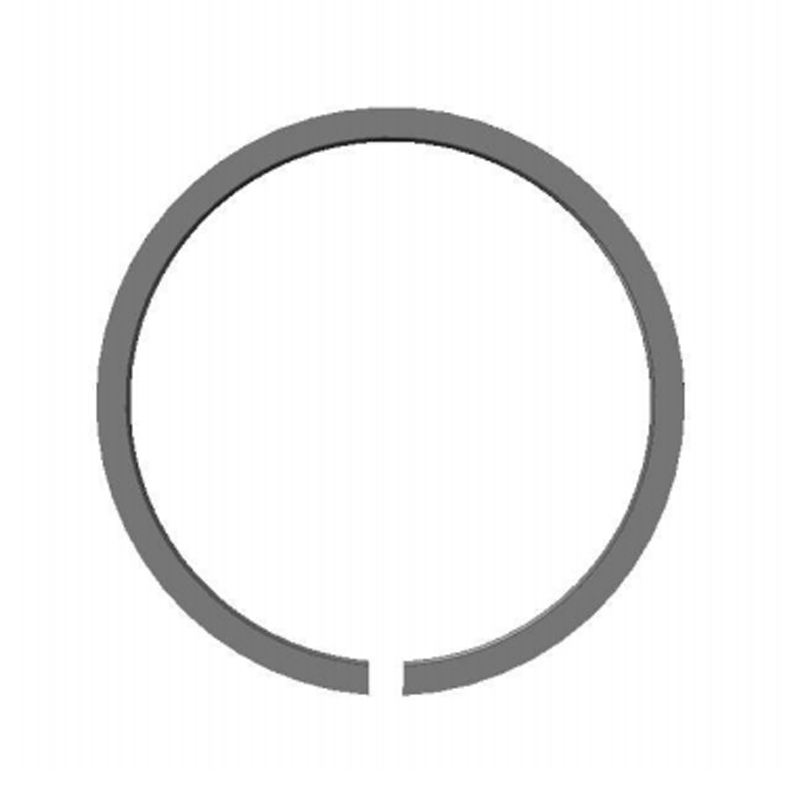
Snap rings, frequently referred to as retaining rings or circlips, serve a highly specific mechanical purpose: they restrict axial movement while maintaining radial clearance within precision assemblies. Unlike threaded fasteners or welded joints, these components rely on elastic deformation to secure themselves within machined grooves. When installed, the ring undergoes controlled expansion or compression, generating a continuous radial force that presses the ring firmly against the groove walls. This mechanical interference effectively locks the component in place, allowing it to withstand significant axial thrust loads without permanent deformation. The engineering advantage lies in their ability to eliminate the need for bulky shoulders, nuts, or additional locking hardware, thereby reducing overall assembly weight and machining time.
The functional design of snap rings centers around the relationship between ring deflection and groove geometry. A properly specified ring must account for the operating load, rotational speed, and thermal expansion of the mating parts. Engineers calculate the required ring thickness and cross-sectional shape based on the expected axial force and the material yield strength. If the groove width is too narrow, the ring cannot seat fully, leading to premature failure under load. Conversely, excessive clearance allows axial play, defeating the retention purpose. Modern applications demand precise tolerance matching, typically within a few thousandths of an inch, to ensure consistent performance across millions of operational cycles. Understanding this load-path relationship is essential before selecting any specific ring variant.
Beyond simple retention, snap rings contribute to vibration damping and noise reduction in high-speed rotating systems. By maintaining precise component alignment, they prevent micro-movements that cause fretting corrosion or bearing misalignment. Their lightweight construction and compact footprint make them indispensable in automotive transmissions, aerospace actuators, and industrial gearboxes. When integrated correctly, these rings transform complex multi-part assemblies into streamlined, highly reliable mechanical units that operate efficiently under demanding conditions.
Exploring Internal vs. External Snap Ring Configurations
The primary classification of retaining rings revolves around their mounting orientation relative to the host component. Internal and external snap rings serve fundamentally different retention scenarios, each requiring distinct groove profiles and installation methodologies. The selection between the two depends entirely on whether the component being secured resides inside a cylindrical housing or around an outer shaft diameter. Confusing these configurations during the design phase leads to improper seating, insufficient load capacity, and immediate assembly failure.
Internal Retaining Rings
Internal retaining rings are designed to fit within a machined bore or housing, expanding outward to lock against the internal groove wall. These rings typically feature lug holes that allow specialized pliers to grip and compress the ring diameter during insertion. Once seated, the ring relies on the surrounding housing structure to absorb radial thrust. They are commonly utilized to secure bearings inside pillow blocks, retain bushings in hydraulic cylinders, and position seals within pump casings. The internal design excels in applications where external protrusions are undesirable or where space constraints prohibit outer retention hardware.
External Retaining Rings
External retaining rings wrap around the outside diameter of a shaft, pin, or threaded rod, compressing inward to snap into a circumferential groove. These rings are engineered to resist outward displacement forces, making them ideal for securing gears on transmission shafts, positioning pulleys on motor spindles, and retaining cotter pins or pivot pins in linkage systems. The external configuration offers easy visual inspection and straightforward tool access during maintenance cycles. However, it requires sufficient radial clearance on the shaft exterior and precise groove machining to prevent stress concentration points.
| Configuration | Load Direction | Primary Application | Tool Access |
| Internal | Radial outward | Housing bore retention | Requires internal pliers |
| External | Radial inward | Shaft component locking | Requires external pliers |
Material Selection and Durability Factors
The longevity of snap rings depends heavily on material composition, heat treatment, and environmental exposure. Standard carbon spring steel remains the most widely used base material due to its excellent fatigue resistance, high yield strength, and cost-effectiveness. After cold coiling and stress-relief annealing, these rings achieve consistent spring rates that maintain retention force across thousands of deflection cycles. However, uncoated carbon steel is vulnerable to rust in humid or corrosive environments, which can compromise structural integrity and increase installation friction.
Stainless Steel Variants
Austenitic and martensitic stainless steels offer superior corrosion resistance for marine, food processing, and chemical handling applications. While slightly less rigid than carbon spring steel, modern stainless formulations maintain adequate tensile strength for most standard retention tasks. Engineers often specify 302 or 316 stainless rings when washdown procedures, saltwater exposure, or aggressive cleaning agents are present. The trade-off involves marginally higher deflection rates under heavy axial loads, which must be compensated through thicker cross-sections or tighter groove tolerances.
Protective Coatings and Surface Treatments
Zinc plating, phosphate coating, and cadmium alternatives provide intermediate protection for carbon steel rings operating in moderately harsh conditions. These surface treatments reduce initial installation friction, prevent galling during repeated assembly cycles, and delay oxidation onset. For high-temperature or abrasive environments, PTFE or molybdenum disulfide coatings minimize wear between the ring and groove walls. Selecting the correct finish ensures that snap rings maintain their mechanical properties without introducing contaminants or compromising dimensional accuracy.
Step-by-Step Installation and Removal Techniques
Proper tooling and technique dictate whether a retaining ring performs reliably or fails prematurely. Using improvised screwdrivers or mismatched pliers can distort the ring geometry, introduce micro-fractures, or scratch the mating groove, leading to inadequate seating and catastrophic axial movement. Always verify plier tip diameter against the lug hole size and confirm the tool matches the internal or external ring orientation before beginning work. Maintaining clean, debris-free grooves and inspecting ring edges for burrs are critical preparatory steps.
During installation, align the plier tips securely within the ring lugs and apply steady, even pressure to compress or expand the ring to the required diameter. Guide the ring squarely into the groove without twisting or angling, ensuring the gap aligns with low-stress regions of the housing or shaft. Once the ring drops into the machined channel, release the pliers slowly and verify complete seating by visually inspecting the circumference and checking for audible clicks. A properly installed ring sits flush with the groove surface and exhibits uniform radial contact along the entire perimeter.
Removal follows a similar controlled approach. Position the plier tips into the lugs, apply gradual pressure to overcome the seated tension, and lift the ring straight out of the groove. Never pry or lever the ring against the mating surface, as this damages precision-machined components and deforms the ring beyond reuse specifications. Wear safety glasses during both installation and removal, as stored elastic energy can cause rings to eject unexpectedly if slipped. Proper technique preserves component tolerances and extends service life across multiple maintenance intervals.
Practical Guidelines for Selecting the Right Snap Ring
Choosing the optimal retaining ring requires evaluating multiple engineering parameters simultaneously. Dimensional compatibility forms the foundation, but load requirements, operating temperature, and cycle frequency equally influence final selection. Relying solely on diameter matching ignores critical performance variables that determine long-term reliability. Engineers must cross-reference application data with manufacturer specifications to ensure the selected snap rings meet or exceed design requirements under real-world conditions.
- Verify exact groove width, depth, and diameter tolerances before procurement to guarantee full ring engagement and proper load distribution across the retention interface.
- Calculate maximum axial thrust and rotational speeds to select appropriate cross-sectional thickness, ensuring the ring withstands dynamic forces without permanent set or fracture.
- Match material grade and surface treatment to environmental exposure, prioritizing corrosion resistance for wet or chemical environments and heat-treated alloys for high-stress applications.
- Confirm compatibility with existing assembly tools and maintenance access points to streamline installation workflows and reduce labor costs during routine servicing.
Final validation involves prototype testing under simulated operating conditions before full-scale deployment. Measuring axial displacement, inspecting groove wear patterns, and verifying retention force after thermal cycling provides concrete data to confirm selection accuracy. By treating snap rings as engineered retention components rather than generic hardware, designers achieve tighter assemblies, improved reliability, and reduced lifecycle maintenance costs across diverse mechanical systems.