English
 中文简体
中文简体
A snap ring for a shaft is one of the most mechanically elegant fasteners in engineering — no threads, no adhesive, no welding, just a sprung ring seated in a groove that holds an entire assembly in axial position. But that simplicity depends entirely on matching the right ring to the shaft, and installing it correctly with appropriate pliers. Get either wrong, and the ring fails silently until a bearing walks off its seat or a gear cluster migrates out of mesh.
Content
- 1 What Is a Snap Ring for a Shaft?
- 2 How Shaft Snap Rings Work: The Mechanics of Retention
- 3 Selecting the Right Snap Ring for Your Shaft
- 4 Snap Ring Pliers: Types, Selection, and Proper Use
- 5 Common Installation Mistakes and How to Avoid Them
- 6 Industry Applications
- 7 When Standard Snap Rings Are Not Enough
What Is a Snap Ring for a Shaft?
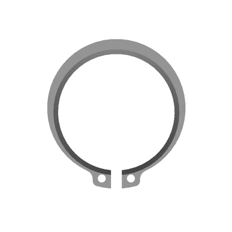
A snap ring for a shaft — also called an external retaining ring, external circlip, or shaft circlip — is a thin, open-ended ring manufactured from hardened spring steel. It seats in a circumferential groove machined into the outer surface of a shaft, where it creates a mechanical shoulder that prevents axially loaded components from sliding off the shaft end.
Unlike threaded fasteners, a shaft snap ring requires no tools for removal of the component itself. The ring is the only element that needs to come out, and with the right snap ring pliers, installation and removal take seconds. This makes shaft snap rings the preferred retention method in assemblies that require periodic maintenance, component replacement, or inspection — from gearboxes and drivetrains to electric motors and hydraulic cylinders.
The snap ring for shaft applications available in standard metric and inch series covers an enormous range of shaft diameters. Metric DIN 471 external circlips for shaft grooves cover diameters from 3 mm to 300 mm. Inch-series equivalents handle shafts from under 1/4 inch up to several inches in diameter, with load ratings that scale accordingly.
How Shaft Snap Rings Work: The Mechanics of Retention
The retention mechanism is based on spring preload. In its free state, an external snap ring has a natural diameter slightly smaller than the shaft groove diameter. To install it, snap ring pliers expand the ring beyond the shaft's outer diameter; once released into the groove, the ring contracts back toward its natural diameter and locks in place under its own spring tension.
The groove does the structural work. Its width matches the ring's cross-section thickness (with a small clearance), and its depth positions the ring so that roughly one-third of the ring's height projects above the shaft surface. That projecting shoulder is what bears axial load from the retained component.
Thrust capacity — how much axial force the ring can resist — depends on three factors: ring cross-section area, material hardness, and groove geometry. Standard DIN 471 rings are rated for specific static and dynamic axial loads per diameter. When load requirements exceed standard ratings, heavy-duty anti-shift external snap rings with reinforced cross-sections provide significantly higher retention capacity without requiring a larger groove.
Selecting the Right Snap Ring for Your Shaft
The specification process follows a logical sequence. Work through each parameter in order and the correct ring becomes unambiguous.
Shaft diameter. This is the nominal ring size. A DIN 471 ring marked "20" installs on a 20 mm shaft. Always verify against the actual measured shaft diameter rather than assuming a nominal value — manufacturing tolerances on shafts affect groove fit and ring seating.
Groove dimensions. The groove must match the ring's specified groove width and groove depth. If the groove is too shallow, the ring will not seat fully and its projecting shoulder will be reduced, lowering thrust capacity. If the groove is too wide, the ring can tilt under axial load and lose contact with the component face. Groove dimensions for DIN 471 rings are tabulated in the standard and should be machined to those tolerances.
Axial load. For low-load applications — retaining a light bearing, a seal housing, or a positioning collar — a standard stamped ring is sufficient. For applications involving thrust loads from helical gears, heavy bearings under preload, or shock-loaded assemblies, verify the ring's rated static thrust against the actual application load with a safety factor.
Operating environment. Carbon spring steel with phosphate finish handles most dry and mildly humid industrial environments. Marine, food-grade, and chemically aggressive environments call for stainless steel options. The snap ring product range includes both carbon steel and stainless variants across standard series.
Special configurations. When the shaft end is inaccessible for axial ring installation, an E-clip (DIN 6799) can be installed radially — slid onto the shaft from the side rather than slipped over the end. For shafts requiring anti-rotation locking, rings with external lugs (DIN 983) provide additional engagement. Non-standard shaft geometries may call for custom-profiled split retaining rings manufactured to print.
Snap Ring Pliers: Types, Selection, and Proper Use
Snap ring pliers are the only tool that should be used for installing or removing shaft snap rings. The pliers engage the small lug holes at each open end of the ring, apply controlled force to expand or compress it, and allow the technician to guide the ring accurately into position. Using a screwdriver, standard pliers, or any improvised tool instead risks deforming the ring, damaging the groove, or sending a ring projectile across the workshop at speed.
Types of Snap Ring Pliers
External snap ring pliers are designed for shaft installation. When the handles are squeezed, the plier tips push outward, expanding the ring so it can be positioned over the shaft and lowered into the groove. For shaft applications, this is the correct tool.
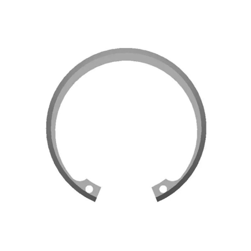
Internal snap ring pliers work in the opposite direction: squeezing the handles brings the tips inward, compressing the ring for bore installation. Using internal pliers on an external ring — or vice versa — will not expand or compress the ring in the right direction and can permanently deform it.
Convertible (reversible) snap ring pliers can switch between internal and external modes, usually via a rotation of the tip assembly or a secondary jaw mechanism. They are useful for technicians who work with both ring types regularly and want to carry a single tool.
Straight-tip vs. bent-tip pliers. Straight tips give direct access when the snap ring groove is at the end of a shaft with clear approach. Bent tips (typically 45° or 90°) reach rings in recessed locations or where the approach angle is restricted by surrounding components — common in automatic transmission servicing and deep-bore engine work.
Choosing the Right Plier Size
Snap ring pliers are sized to match a range of ring diameters. The plier tip pins must fit the ring's lug holes without play; an oversized pin will not engage the hole properly, and an undersized pin may slip out under the spring load of a large ring. Most professional plier sets cover a range from small (under 15 mm) through medium (15–60 mm) to large (60 mm and above), with heavier-gauge pliers needed for large-diameter rings that have significant spring tension.
Step-by-Step Installation of a Shaft Snap Ring
- Clean the shaft groove thoroughly. Any debris in the groove prevents the ring from seating fully and reduces its rated thrust capacity.
- Select the correct external snap ring pliers for the ring size. Verify the tip pins fit the lug holes cleanly.
- Insert the plier tips into both lug holes simultaneously. Do not engage only one side — this twists the ring and can crack it.
- Squeeze the handles to expand the ring just enough to clear the shaft outer diameter. Over-expansion weakens the ring; expand only as much as necessary.
- Position the expanded ring directly over the groove location and release the handles slowly, allowing the ring to contract into the groove.
- Confirm full seating by running a fingernail or probe around the entire ring circumference. Every section of the ring should be flush within the groove — no bridging, no lifted sections.
Removal
Removal reverses the process. Insert the plier tips, expand the ring clear of the groove walls, and lift it straight off the shaft. Inspect the removed ring for deformation, cracks, or permanent set before reusing. A ring that has been over-expanded — or shows flat sections on the cross-section — should be replaced, not reinstalled.
Common Installation Mistakes and How to Avoid Them
Most snap ring failures in service trace back to installation errors rather than material defects. The following problems are well-documented and entirely preventable.
Incomplete groove seating. The ring sits proud of the groove on one or more sections, either because the pliers were not fully released or because groove debris prevented full engagement. The ring then fails under the first significant axial load. Prevention: always visually and tactilely verify 360° seating.
Over-expansion during installation. Forcing the ring past its elastic limit to clear an obstacle permanently reduces its spring preload. The installed ring may appear normal but will not maintain the groove contact pressure needed for rated retention. Prevention: if a ring cannot be expanded enough to clear the shaft without excessive force, check whether the correct ring size has been selected.
Wrong ring specification. Installing an internal ring in a shaft groove — or vice versa — is surprisingly common when mixed stock is present. The rings may appear similar; the geometry is not. Always verify ring type before installation.
Groove damage from removal tools. Prying at a seated ring with a screwdriver creates stress risers in the groove that can propagate into shaft cracks under cyclic loading. Use pliers.
Industry Applications
Shaft snap rings appear wherever rotating or sliding components mount on shafts — which encompasses a substantial portion of mechanical engineering.
In automotive transmissions, snap rings for shafts retain planetary gear sets on sun gear shafts and hold clutch drum assemblies in position. The compactness of the ring allows tight axial spacing between components that would be impossible with threaded collars.
In electric motors and generators, snap rings locate rotor bearings on motor shafts. At high rotational speeds, the ring must be precisely seated with no imbalance contribution — which means correct sizing and proper installation matter as much as material specification.
In agricultural and construction equipment, external snap rings on PTO shafts, hydraulic actuator rods, and wheel hub assemblies must resist both axial loads and the vibration and impact loads typical of off-highway operation. Phosphate-finished carbon steel handles most of these environments; severely corrosive conditions call for stainless alternatives available through the external circlip product range.
In consumer and industrial appliances, snap rings on pump shafts, fan motor shafts, and actuator assemblies provide low-cost, reliable retention in moderate-load conditions where the ring is rarely serviced and must perform correctly for the product's service life.
When Standard Snap Rings Are Not Enough
Standard DIN 471 rings cover the vast majority of shaft retention requirements. When they do not, the options are well-defined.
For higher thrust loads, move to a ring with greater cross-section thickness or a two-lug heavy-duty design. For assemblies with anti-rotation requirements, external rings with lugs (DIN 983) add engagement features that prevent the ring from rotating in the groove under torque. For shafts with non-standard profiles, tight axial spacing, or unusual material requirements, custom-manufactured retaining ring solutions can be produced to engineering drawings with full dimensional control.
The key is never to compromise on ring selection because a non-standard size is inconvenient to source. A correctly specified snap ring is a passive, maintenance-free component. An undersized or incorrectly installed ring is a scheduled failure waiting to happen.